
DIY and Learning Resources
The first and most important aspect of any piece of electronic equipment is the power supply. This brief tutorial is intended to cover some basic principles to help you Do It Yourself. Most synthesizers require bi-polar power supplies capable of supplying positive voltage and negative DC voltage. How do we do that?
First, a basic, basic schematic. Some of the symbols are wrong, but the information is good. (Click To Enlarge)

Let's go step-by-step from here.
The first connection is from a center tapped transformer - like this one available at Radio Shack.

If you read the datasheet, you'll notice the transformer has two wires for 120V input
(BE CAREFUL WITH MAINS VOLTAGE! - More on that later)
and 3 wires on the other side for output. The Datasheet says to use 1 Yellow + 1 Black for 12.6 Volt output or use 2 Yellows for 26.2 Volt output.
Since we want bi-polar 12V, we will use the black wire as our ground wire and the two Yellow wires as our AC inputs.
Therefore, our input will look like this:

More importantly, this is what it would look like if you looked at it with an oscilloscope:
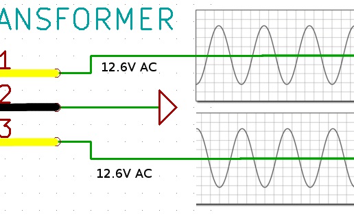
Notice how the AC signals are out of phase with each other? This will be important as we reach the next step.
Notice the 4 diodes in the following image.
Since diodes only pass current in one direction, the diodes in each part of the circuit only allow the respective charge in that part of the circuit.
The picture below will explain it better than words :)
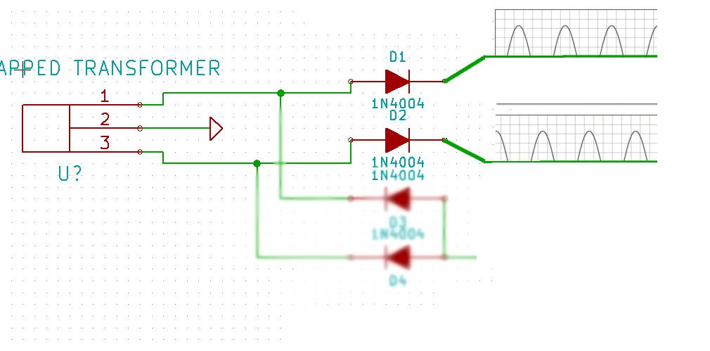
When you combine the outputs from the forward biased diodes, the result is the same as if you chopped a sine wave in half and flipped the negative going side to be positive.
 This is effectively what we're doing in full wave rectification.
The only difference is we must use two different sine waves, one out of phase with the other, and simply combine the respective positive or negative parts of both waves.
This is effectively what we're doing in full wave rectification.
The only difference is we must use two different sine waves, one out of phase with the other, and simply combine the respective positive or negative parts of both waves.
At this point, the adafruit tutorial covers it much better than I could.
Plus their graphics are better (....as I'm sure you've noticed mine are of inferior quality).
http://learn.adafruit.com/power-supplies/transformer-based-ac-slash-dc-converters
From there, the basic parts of the circuit are as follows:
- Filtering capacitors. Capacitors store charge. Therefore, these capacitors act as filters, evening out the charge. Capacitors of different values filter out different frequencies. Or put simply "Big capacitors for big ripples, little capacitors for little ripples". When you hear someone talk about power supply ripple, this is what they mean. This is important because this ripple makes an exact DC voltage not be that exact DC voltage at any given time.
- Voltage Regulators (or a different precision voltage reference). A voltage regulator, or sometimes known as a power transistor, compensates for fluctuations in voltage and current. It serves to make a DC voltage as stable as possible. A better voltage regulator makes a voltage more stable, hence the need for precision references in some circuits. It's important to note
To be continued.... this is a work in progress